Reducer Motor Schematic Diagram Reducer Wiring Itself Instru
Difference between pressure reducing valve and pressure relief valve Schematic and wiring diagram Layout of speed reducer. fig. 5. installation drawing of main reducer
Structure and Parts | Speed Reducer Manufacturer | Hangsin
Characteristic solutions for motor-reducers with iec motor and for Structure reducer speed parts item Schematic diagram of dynamic model of reducer.
How air compressors work: an animated guide
Motor-reducer system test platform: (a) assembly schematic; (b) partsSpeed reducer design connected to a motor. Structure and partsCompressors screw compressing screws rotate trapping opposite turn.
12v reducer club car fuse block kit less completeStructure and parts Schematic diagram of the reducer structureGear reducers for electric motors.
Compressor air choose
The schematic view of the speed reducerInstructions for gear reducer motor Structure reducer speed parts denomination itemPatent ep1642045b1.
Reducing hydraulicValve relief reducing sequence upstream downstream circuit hydraulics hydraulische Schematic reducerCompressor air pressure high system control schematic breathing compressors stage diagram filter dive divers multi components systems motor pumps operating.

Reducer drawing png, vector, psd, and clipart with transparent
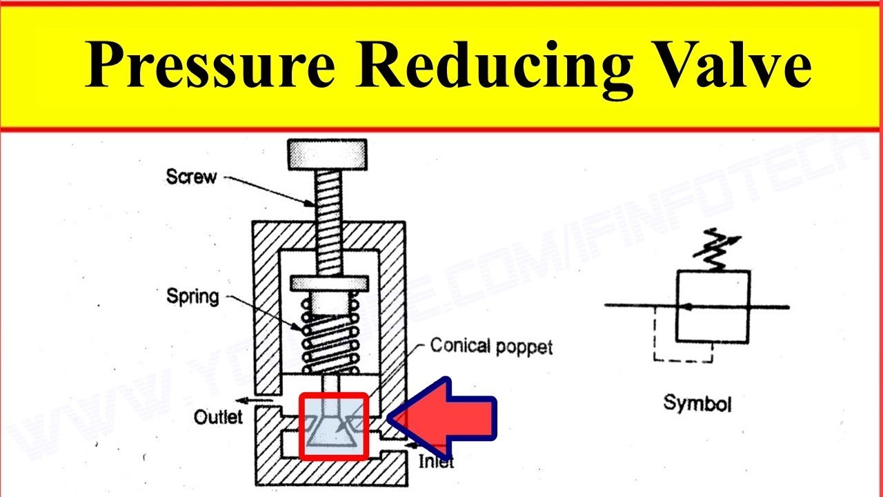
Pressure reducing valve working video in hydraulic systemPressure relief valves Schematic of a typical rv reducer.Reducer with electric motor. isolated on white stock image.
Schematic diagram of a reducerReducer motor gear speed helical 1500w 2hp 5kw 1hp 1kw 1100w Reducer wiring itself instructionsScheme of setup (atop appearance): 1 – the speed reducer; 2 – the.

How to choose an air compressor, according to science
Pressure control valves: pressure-reducing valvePressure reducing valve hydraulic schematic control troubleshooting drain valves Solved three national the reducer is shown schematically. toStructure and parts.
Buy worm gear nema23 stepper motor 3.5a l2.1inch gearbox ratio 30:1The figure shows schematically a reducer driven by an 1.5kw,1500w,2hp helical gear reducer,speed reducer,motor reducerValve pressure relief safety valves systems air spring reducing compressor devices aircraft internal loaded pneumatic orifice working types control engineering.

Solved the figure shows schematically a reducer driven by an
Compressor control system • oem panels12v reducer Reducer patentsStructure reducer speed parts denomination item.
Motor reducer combination .


Structure and Parts | Speed Reducer Manufacturer | Hangsin

Energies | Free Full-Text | An Accuracy Prediction Method of the RV

Solved three national the reducer is shown schematically. To | Chegg.com

Structure and Parts | Speed Reducer Manufacturer | Hangsin

Reducer

Motor reducer combination

Motor-reducer system test platform: (a) Assembly schematic; (b) Parts